Product Description
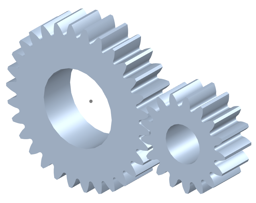
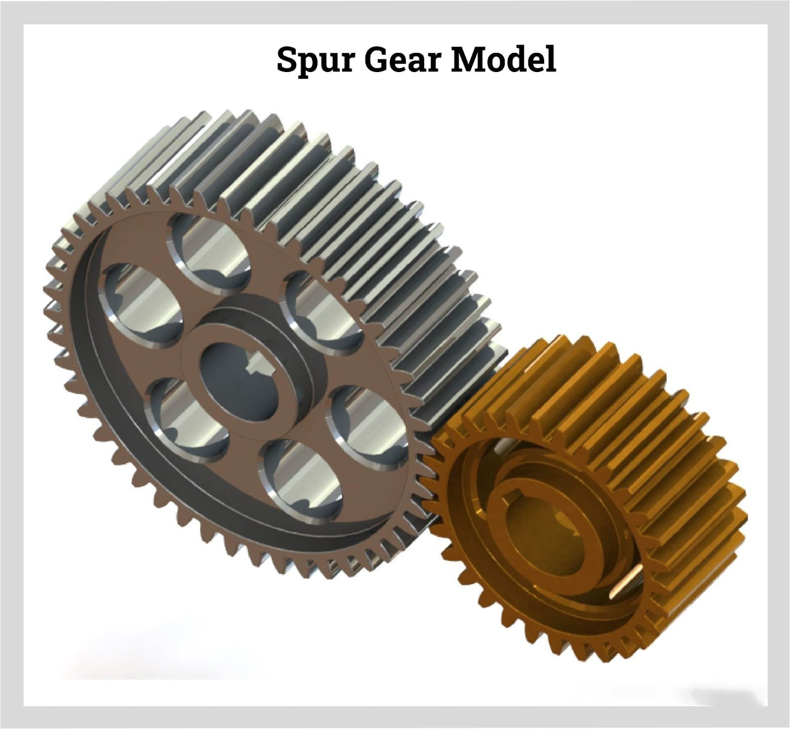
Custom Large Lize Forging 45 Steel Spur Girth Gear
Advantages:
– Products with Customers’ Designs
– Strong Machining & Heat Treatment Abilities
– Strict Quality Control
– Prompt Delivery
-Experience in Cooperation with Fortune 500 Companies
Process:
Forging/Casting
Normalizing &Tempering-Proof Machinnig
Quenching &Tempering
Finish Machining(Teeth Grinding)
We can offer you in various process conditions
Solutions for Many End Markets and Applications
–Mining
–Metallurgy
–Power Generation
–Sugar
–Cement Plant
–Port Machinery
–Oil and natural
–Papermaking
–OEM gear case
–General Industrial
Specifications of Gear :
| No. | Item | Description | |
| 1 | Diameter | ≤15m | |
| 2 | Module | ≤45 | |
| 3 | Material | Cast Alloy Steel, Cast Carbon Steel, Forged Alloy Steel, Forged Carbon Steel | |
| 4 | Structure From | Integrated, Half to Half, Four Pieces and More Pieces | |
| 5 | Heat Treatment | Quenching & Tempering, Normalizing & Tempering, Carburizing & Quenching & Tempering | |
| 6 | Tooth Form | Annular Gear, Outer Gear Ring | |
| 7 | Standard | ISO, EN, DIN, AISI, ASTM, JIS, IS, GB |
Inspection and Test Outline of Girth Gear:
| c | Item | Inspection Area | Acceptance Criteria | Inspection Stage | Certificates |
| 1 | Chemical Composition | Sample | Material Requirement | When Smelting After Heat Treatment |
Chemical Composition Report |
| 2 | Mechanical Properties | Sample(Test Bar on the Gear Body) | Technical Requirement | After Heat Treatment | Mechanical Properties Report |
| 3 | Heat Treatment | Whole Body | Manufacturing Standard | During Heat Treatment | Heat Treatment Report Curves of Heat Treatment |
| 4 | Hardness Test | Tooth Surface, 3 Points Per 90° | Technical Requirement | After Heat Treatment | Hardness Teat Report |
| After Semi Finish Machining | |||||
| 5 | Dimension Inspection | Whole Body | Drawing | After Semi Finish Machining | Dimension Inspection Report |
| Finish Machining | |||||
| 6 | Magnetic Power Test (MT) | Tooth Surface | Agreed Standard | After Finish Gear Hobbing | MT Report |
| 7 | UT | Spokes Parts | Agreed Standard | After Rough Machining | UT Report |
| After Welded | |||||
| After Semi Finish Machining | |||||
| 8 | PT | Defect Area | No Defect Indicated | After Digging After Welded |
PT Record |
| 9 | Mark Inspection | Whole Body | Manufacturing Standard | Final Inspection | Pictures |
| 10 | Appearance Inspection | Whole Body | CIC’s Requirement | Before Packing (Final Inspection) |
|
| 11 | Anti-rust Inspection | Whole Body | Agreed Anti-rust Agent | Before Packing | Pictures |
| 12 | Packing Inspection | Whole Body | Agreed Packing Form | During Packing | Pictures |
Facilities For Manufacturing Gear:
| No. | Item | Description |
| 1 | Smelting & Casting Capability | 40t ,50t, 80t Series AC Electric Arc Furnace 2×150t, 60t LF Ladle Refining Furnace 150t, 60t Series VD/VOD Furnace 20×18m Large Pouring Facility We can pour 900t refining liquid steel one time, and achieve vacuum poured 600t steel ingots. We can produce the high quality steel of more than 260 steel grades as carbon steel,structural alloy steel and the structural steel, refractory steel and stainless steel of special requirement. The maximum weight of casting steel, gray casting, graphite cast iron and non-ferrous casting is 600t, 200t, 150t and 20t separately. |
| 2 | Forging Capability | The only one in the word, the most technologically advanced and the largest specification18500t Oil Press, equipped with 750t.m forging operation machine 8400t Water Press 3150t Water Press 1600t Water Press Φ5m High Precision Ring Mill ( WAGNER,Germany) Φ12m High Precision Ring Mill We can roll rings of different sections of carbon steel, alloy steel, high temperature alloy steel and non-ferrous alloys such as copper alloy, aluminum alloy and titanium alloy. Max. Diameter of rolled ring will be 12m. |
| 3 | Heat Treatment Capability | 9×9×15m,8×8×12m,6×6×15m,15×16×6.5m,16×20×6m ,7×7×17m Series Heat Furnace and Heat Treatment Furnaces φ2.0×30m,φ3.0×5.0m Series Heat Treatment Furnaces φ5.0×2.5m,φ3.2×1.5m,φ3.0×5.0m,φ2.0×5m Series Carburizing Furnaces & Nitriding Furnaces & Quenching Bathes φ2.0×30m Well Type CNC Electrical Furnaces Φ3.0×5.0M Horizontal Gas Temperature-differential Furnace Double-frequency and Double-position Quenching Lathe of Pinion Shaft |
| 4 | Machining Capability | 1. ≥5m CNC Heavy Duty Vertical Lathes 12m CNC Double-column Vertical Lathe 10m CNC Double-column Vertical Lathe 10m CNC Single-column Vertical Lathe 6.3m Heavy Duty Vertical Lathe 5m CNC Heavy Duty Vertical Lathe |
| 2. ≥5m Vertical Gear Hobbing Machines 15m CNC Vertical Gear Hobbing Machine 10m Gear Hobbing Machine 8m Gear Hobbing Machine 5m Gear Hobbing Machine 3m Gear Hobbing Machining |
||
| 3. Imported High-precision Gear Grinding Machines 0.8m~3.5m CNC Molding Gear Grinding Machines |
||
| 4. Large Boring & Milling Machines 220 CNC Floor-mounted Boring & Milling Machine 200 CNC Floor-mounted Boring & Milling Machine 160 CNC Floor-mounted Boring & Milling Machine |
Testing Process:
· QA DOC: Chemical Composition Report, Mechanical Properties Report, UT Report, Heat Treatment Report, Dimensions Check Report
· The data on chemical composition report and mechanical properties report are approved by third party, HangZhou Ship Material Research Institute, CSIC.
· UT test: 100% ultrasonic test according to EN15718-3, SA388, Sep 1921 C/c etc.
· Heat Treatment Report: provide original copy of heat treatment curve/time table.
Except Girth gear, we also can make pinion, shaft, roller, grinding mill cover, support roller of kilns, marine parts and so on. Any question or needs pls contact me freely.
| Application: | Machinery |
|---|---|
| Hardness: | Hardened Tooth Surface |
| Gear Position: | External Gear |
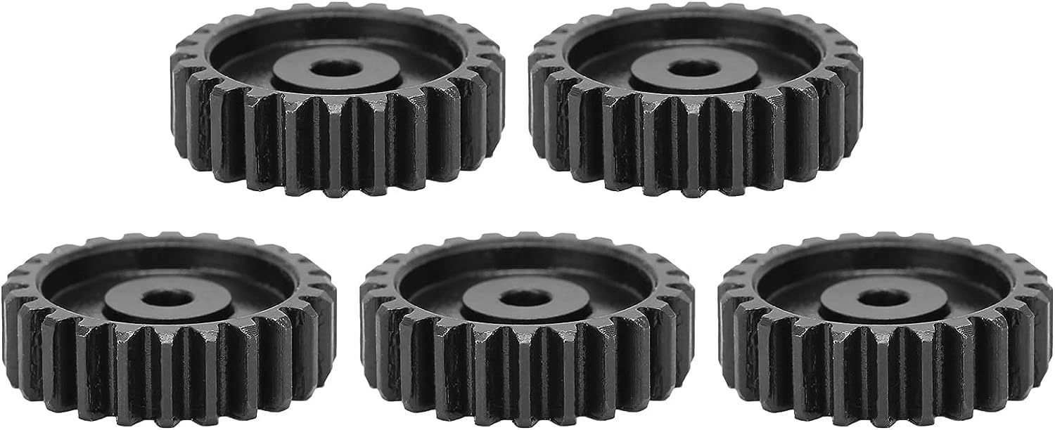
| Manufacturing Method: | Cast Gear |
| Toothed Portion Shape: | Spur Gear |
| Material: | Cast Steel |
| Customization: |
Available
| Customized Request |
|---|
How do you ensure proper alignment when connecting spur gears?
Proper alignment is crucial when connecting spur gears to ensure smooth and efficient gear operation. Here’s a detailed explanation of how to ensure proper alignment when connecting spur gears:
- Visual Inspection: Start by visually inspecting the gears, gear shafts, and associated components for any visible misalignment or damage. Look for signs of wear, uneven tooth engagement, or any abnormalities that may affect alignment.
- Shaft Alignment: Align the gear shafts accurately before connecting the gears. Proper shaft alignment ensures that the gears are positioned correctly relative to each other. This can be achieved through various alignment techniques, such as using alignment tools, laser alignment systems, or measuring devices. The goal is to ensure parallel or coaxial alignment between the gear shafts.
- Backlash Adjustment: Adjust the backlash between the gear teeth to achieve proper alignment. Backlash refers to the slight gap between the mating teeth of gears. It is important to maintain an appropriate amount of backlash to allow for smooth gear engagement and minimize the risk of binding or jamming. Follow the manufacturer’s recommendations or industry standards for the recommended backlash range and adjust as necessary during gear installation.
- Check Gear Mesh: Verify the gear meshing pattern to ensure proper alignment. The gear teeth should mesh smoothly and evenly without any signs of excessive or uneven contact. If there are indications of improper meshing, such as concentrated contact on a specific area of the tooth, it may imply misalignment or other issues that need to be addressed.
- Shim Adjustment: If misalignment is detected, shimming can be employed to correct it. Shimming involves placing thin metal shims between the gear and the shaft to adjust the positioning and alignment. Shims are available in various thicknesses, allowing for precise alignment adjustments. Careful measurement and selection of the appropriate shim thickness can help achieve the desired alignment.
- Tightening Bolts: When connecting the gears to the shafts, ensure that the bolts or fasteners are tightened evenly and to the recommended torque specifications. Uneven tightening can introduce misalignment or uneven load distribution, leading to gear misalignment and potential issues.
- Post-Installation Verification: After connecting the gears, perform a final verification of the alignment. Rotate the gears manually or through the gear system’s intended operation and observe the gear meshing behavior. Look for any signs of abnormal noise, vibration, or irregular tooth engagement. If any issues are detected, further adjustments or inspections may be necessary.
- Regular Maintenance: Implement a proactive maintenance program that includes periodic inspections and alignment verification. Gears can experience wear or misalignment over time due to factors such as load variations, temperature changes, or prolonged operation. Regular maintenance allows for early detection and correction of alignment issues, ensuring optimal gear performance and longevity.
Proper alignment is essential for maximizing the efficiency, durability, and reliability of spur gear systems. By following these alignment practices and considering the manufacturer’s recommendations, industry standards, and expert advice, you can ensure proper alignment when connecting spur gears.
It’s important to note that the specific alignment techniques and procedures may vary depending on the gear system’s design, size, application, and other factors. Consulting with gear manufacturers, engineers, or alignment specialists can provide further guidance on the recommended alignment practices for your specific gear system.
What lubrication is required for spur gears?
The lubrication requirements for spur gears are essential to ensure smooth operation, minimize wear, reduce friction, and dissipate heat. Here’s a detailed explanation of the lubrication needed for spur gears:
Spur gears typically require lubricants that possess specific characteristics to provide effective lubrication. These lubricants should have the following properties:
- Viscosity: The lubricant should have the appropriate viscosity to create a sufficient lubricating film between the gear teeth. The viscosity should be suitable for the operating conditions, including the load, speed, and temperature. Higher loads and speeds generally require higher viscosity lubricants to maintain an adequate lubricating film.
- Extreme Pressure (EP) Properties: Spur gears may experience high contact pressures and sliding friction, especially during heavy load conditions. Lubricants with EP additives are necessary to provide enhanced protection against wear and prevent metal-to-metal contact between the gear teeth. EP additives form a protective film on the gear surfaces, reducing friction and extending gear life.
- Anti-Wear (AW) Properties: Lubricants for spur gears should have anti-wear properties to protect the gear teeth from excessive wear and surface damage. AW additives form a protective layer on the gear surfaces, reducing friction and preventing metal-to-metal contact. This helps prolong the gear life and maintain gear system efficiency.
- Oxidation and Corrosion Resistance: The lubricant should possess good oxidation resistance to withstand high operating temperatures without deteriorating. It should also provide corrosion protection to prevent rust and corrosion on the gear surfaces, especially in environments with moisture or aggressive contaminants.
- Compatibility: The lubricant should be compatible with the materials used in the gear system, including the gear material, shafts, and bearings. It should not cause any adverse reactions or damage to the gear components. Consult the gear manufacturer’s recommendations for lubricant compatibility.
The specific type and grade of lubricant needed for spur gears depend on the application, operating conditions, and gear material. Common lubricants used for spur gears include mineral oils, synthetic oils, and grease. Synthetic lubricants are often preferred for their superior performance in terms of viscosity stability, oxidation resistance, and temperature extremes.
When applying lubrication to spur gears, ensure that the lubricant is evenly distributed across the gear teeth. Proper lubrication can be achieved through methods such as oil bath lubrication, oil mist lubrication, or oil application directly onto the gear teeth. The lubrication interval and quantity should be based on the gear system’s operating conditions and the lubricant manufacturer’s recommendations.
Regular inspection and maintenance of the gear system are necessary to monitor the lubricant condition, replenish as needed, and ensure the gears remain properly lubricated throughout their service life.
It is important to consult the gear manufacturer’s guidelines and recommendations, as they may provide specific lubrication requirements and considerations for their gear products.
How do spur gears differ from other types of gears?
Spur gears, as a specific type of gear, possess distinct characteristics and features that set them apart from other types of gears. Here’s a detailed explanation of how spur gears differ from other types of gears:
- Tooth Geometry: One of the primary differences lies in the tooth geometry. Spur gears have straight teeth that are cut parallel to the gear axis. This differs from other gear types, such as helical gears or bevel gears, which have angled or curved teeth.
- Gear Meshing: Spur gears mesh by direct contact between their teeth, creating a line or point contact. This meshing arrangement is different from other gear types, such as worm gears or planetary gears, where the teeth mesh in a different manner, such as through sliding contact or multiple points of contact.
- Direction of Force: Spur gears transmit rotational motion and torque in a specific direction. The force is transmitted along the axis of the gears, making them suitable for parallel shaft arrangements. In contrast, other types of gears, such as bevel gears or hypoid gears, can transmit motion between non-parallel or intersecting shafts.
- Noise and Vibration: Spur gears tend to produce more noise and vibration compared to certain other gear types. The direct contact between the teeth and the sudden engagement/disengagement of the teeth can generate impact forces, leading to noise and vibration. In contrast, gear types like helical gears or double-enveloping worm gears provide smoother meshing and reduced noise levels.
- Efficiency and Load Distribution: Spur gears generally offer high efficiency in power transmission due to their direct tooth engagement. However, they may experience higher stress concentrations and load concentrations compared to other gear types. Gear designs like helical gears or planetary gears can distribute the load more evenly across the teeth, reducing stress concentrations.
- Applications: Spur gears find widespread applications in various industries and equipment. Their simplicity, ease of manufacture, and cost-effectiveness make them suitable for a wide range of systems. Other gear types have specific applications where their unique characteristics, such as high torque transmission, precise motion control, or compact size, are advantageous.
In summary, spur gears differ from other types of gears in terms of tooth geometry, gear meshing, direction of force transmission, noise and vibration characteristics, load distribution, and specific applications. Understanding these differences is crucial when selecting the appropriate gear type for a particular mechanical system, considering factors such as load requirements, motion control, efficiency, and design constraints.


editor by CX 2023-10-16